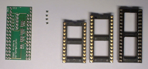
1.
|
Turn over the PCB and solder the
SMD resistors onto their pads. Please refer to the main page for a
description of how many of the resistors are needed for the version of
the adaptor you want to build and onto which pads they have to be
installed.
The easiest way to solder the resistors is the following: add some
solder to one of the pads, then place the resistor there with a pair of
small tweezers and heat the solder pad again. The resistor will now be
glued into place. Now heat the other pad and add some solder, and be
sure not to heat the pad too long, or the first pad will get loose
again.
Now you can put the socket adaptor into place, the thicker pins are
inserted into the holes. See the next step for more details.
|
|
2.
|
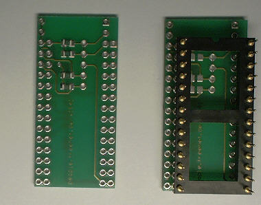
You have two options to install
the adaptor socket: low profile or high profile. If you are going to
install the adaptor into a machine with limited space, choose the low
profile version as shown on the left side: As an extra step, one row of
pins has to be cut off with a wire cutter to allow the socket for the
Flash chip to be installed. In the picture, the right row has been cut
off. In the high profile version, the adaptor socket is only inserted
as
far that the Flash socket can be installed without problems. After
cutting off the pins (if needed) solder the pins from the top side of
the board.
If you use a precision IC socket you probably won't have to cut off any
pins for the low profile version. This depends a lot on the type of IC
socket and socket adaptor you use.
|
|
3.
|
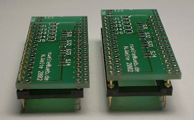
Now install the IC socket from
the top side and solder it from the bottom side. Soldering the low
profile version is a little bit tricky, because some pins are hidden
behind the plastic bars of the socket adaptor. When you put the
soldering iron carefully from one side and apply solder from the other
side of these bars, the socket can be soldered without melting the
plastic.
|
|
4.
|
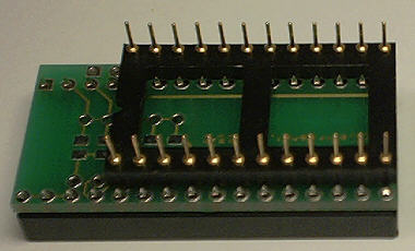
As the final step, solder the
wires coming from the banking switches (if you have any) to the jumper
connectors J1 to J5. Then you can insert the Flash chip and install the
adaptor in your machine.
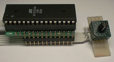
The picture shows a hex coding switch that allows the use of 16
different 8kB ROM images with a single switch. Unfortunately such a
switch costs more than EUR 3.00, so I don't have them in stock.
|
|


