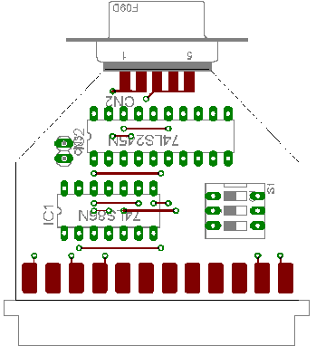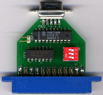


The following components are needed:
| IC1 | 74LS86 | (quad xor gate for inverting the signals) |
| IC2 | 74LS245 | (octal bus transceiver to buffer the signals) |
| S1 | triple DIP switch | |
| CN1 | Userport plug | |
| CN2 | female DB9 socket | |
| CN3 | dual pin header | +5V supply (e.g. from Datasette port) |
Here are two pictures that show the device and the part diagram:
 |
 |
| The prototype, still missing CN3 | Part layout (click to get larger version) |
 |
|
| The final product (only 10 made) |
Just plug the adaptor onto the Userport of your PET, connect a +5V
source to CN3 and connect your monitor to CN2. EGA and Multisync
monitors must be set to 8 or 16 color mode, or the resulting picture
may
have a blue background. If the picture is not good, invert each signal
with the DIP switches until the picture is good (1: video signal, 2:
vsync, 3:hsync). Some monitors use the sync polarity to switch between
(color) modes, others need the correct polarity on both sync signals to
lock onto them at all.
I use this adaptor mostly for repairing old PET and CBM computers,
because the internal monitor can then be removed from the unit to allow
easier access to the mainboard. Sometimes it's also unknown if the
monitor still works at all, and this adaptor offers some help in
testing
this. I also prefer not to power the monitor up and down very often
when
running tests on the mainboard itself.