Pi1541 ist ein zyklusgenauer Commodore 1541-Plattenlaufwerk-Emulator, der auf einem Raspberry Pi 3B, 3B + oder 3A + laufen kann.
Commodore 1581-Emulation wird seit V1.13 unterstützt!
Die Software ist kostenlos und ich habe mich bemüht, die Hardware so einfach und kostengünstig wie möglich zu gestalten.
Pi1541 bietet Ihnen eine SD-Kartenlösung für die Verwendung von D64-, D81-, G64-, NIB- und NBZ-Commodore-Festplatten-Images auf echten 8-Bit-Computern von Commodore, z. B.
Commodore 64
Commodore 128
Commodore 16
Commodore 16
Commodore Plus4
Unterstützung
Wenn Sie mich unterstützen möchten, freuen wir uns über jede Spende. Ich werde mich bemühen, das Projekt weiter zu verbessern.
Andere profitieren von meiner Arbeit.
Alles, was ich frage, ist, dass, wenn Sie nicht selbst bauen und bereit sind, andere zu bezahlen, bitte den Wert meiner Bemühungen berücksichtigen und mir etwas Unterstützung zeigen, danke.
PayPal
Für diejenigen, die mich auf Patreon unterstützen möchten.
Herunterladen
The latest binaries for setting up an SD card can be downloaded here.
If have already set up an SD card and are just looking for the latest kernel.img then you can get it here.
Source code.
What's New in V1.19?
Old Versions.
Default Options.txt file.
A disk image containing FB64
News
Wenn Sie die Option B bauen, verwenden Sie bitte Original-Markenteile.
Menschen berichten, dass die Verwendung von nicht benannten chinesischen Hex-Invertern dazu führen kann, dass einige Festplatten-Images nicht funktionieren.
Ghosts'n Goblins Arcade kann verwendet werden, um die Leistungsfähigkeit Ihres Hex-Wechselrichters zu testen.
Wenn der Titelbildschirm beschädigt ist, ersetzen Sie den Hex-Inverter-IC durch eine echte Markenversion.
Ab Version V1.16 werden nun USB-Laufwerke unterstützt (!!!! EXPERIMENTAL !!!! Es treten Probleme auf, Verwendung auf eigene Gefahr).
Ab Version V1.13 wird auch das Laufwerk Commodore 1581 emuliert.
Kris Sekula hat eine großartige Zusammenfassung geschrieben, die zeigt, wie einfach es ist, ein Kabel herzustellen, das funktioniert.
Danke Kris!
In letzter Zeit gab es einige Verwirrung mit Titeln, die einen Plattenwechsel erfordern.
Mein Freund Jarkko Lehti hat ein großartiges Video gemacht, in dem erklärt wird, wie es funktioniert.
Hintergrund
Like most people I was a little disappointed in the SD2IEC offerings (being very hit and miss with their compatibility) and the hard to order, FPGA solutions were out of my budget.
Inspired by projects such as Peter Edwards' Tapuino and David Banks' PiTubeDirect I set about implementing a 1541 on a Raspberry Pi. My the goal was to make a highly compatable, inexpensive SD card solution for all Commodore
8 bit machines.
I am yet to get it to work on a Pi Zero (as this would be a truly inexpensive solution), but maybe one day.
The Commodore 1541 disk drive is a computer itself. It consists of a CPU, ROM, RAM, IO devices and the drive mechanics. Due to the popularity of Commodore machines and the subsequent proliferation of software created for them, all kinds of exotic fast loaders and copy protection schemes were developed.
As a consequence an inexpensive, cycle exact, SD card solution has taken longer than other systems to come to fruition.
How does Pi1541 differ from SD2IEC?
Unlike SD2IEC, Pi1541 emulates a 6502 and the two 6522s. Any code it is asked to run is run in a cycle exact way. SD2IEC supports a limited set of fast loaders by attempting to guess the fast loader from the code sent to it. SD2IEC will not, and cannot, execute the code, it just simulates the communication protocoles. As a consequence only a small amount of popular fast loaders are supported. As Pi1541 can execute code on its emulated 6502 core it supports a vast range of fast loaders (games and demo scene) even copy protected originals.
Background
When I started out, I had no way of selecting disk images using the Pi's screen and keyboard. I used NBLA000�s excellent CBMFileBrowser that all SD2IEC users would be familiar with. CBMFileBrowser runs on the target Commodore computer and allows you browse and select diskimages using that target computer. In order to do this I had to implement minimal SD2IEC commands. This way, folders can be navigated and
disk images selected as, at this level the Pi behaves like a SD2IEC device. But once a
disk image has been selected the Pi drops down into full cycle exact emulation
and compatibility is near 100%.
Subsequently I have implemented file browsing and selection using the Pi's screen and keyboard. I was going to remove SD2IEC support but others have convinced me to leave it in. Be warned though; the bare minimum functionality was implemented and was initially only used for testing. Going forwards I hope others will implement the full functionality.
Currently when Pi1541 boots it will be in browser mode (or SD2IEC mode)
In this mode Pi1541 will support very minimal SD2IEC commands. Basicaly you can load PRG files and browse folders and images.
(Multiple channels and Saving are also supported for sequentual files only)
Once a valid disk image or images have been selected Pi1541 will drop down into emulation mode.
In full emulation mode
reading and writing are supported. To simulate a write protected disk, set the disk image's file on the SD card to read only.
Note: writing is only supported for D64 and G64 disk images.
Note: when writing back to a disk, Pi1541 cannot make a track longer than the original image's track length. This is generally not an issue.
Setup
To use Pi1541 you will need a Raspberry Pi 3B (or 3B+), an SD card, a cable,
free firmware from the Raspberry Pi Foundation and a valid Commodore 1541 ROM
file.
The cable was designed to be as simple and inexpensive as possible.
SD CARD SETUP
1. Format an SD card to Fat32.
2.
Download the Raspberry Pi Firrmware from the Raspberry Pi Foundation.
3. Once downloaded Unzip the archive.
4. Copy the 3 files (bootcode.bin, fixup.dat and start.elf
(found in firmware-master\boot)) into the root folder of your SD card.
2. Unzip the supplied zip file (Pi1541.zip) to the blank SD card.
(This will create a folder called 1541 in the root folder of the SD card. This
is where you can place your Commodore disk images and folders).
3. Copy over a file that contains a 1541 ROM image (eg
vice-3.1\DRIVES\dos1541) into the root folder of the SD card. The ROM must
be called dos1541 or d1541.rom or d1541II or Jiffy.bin.
4. (OPTIONAL) Copy over a file that contains a CBM font ROM (eg
vice-3.1\C64\chargen) into the root folder of the SD card. The ROM must
be called chargen.
5. Copy your disk images and folders into the 1541 folder
now found on the SD card.
6. Create a cable.
CABLE
Commodore computer's can produce 5V on their serial ports. Raspberry Pi's can only tolerate 3.3V on their GPIO pins. Unfortunatly this complicates the cable design. A I2C Bi-Directional Logic Level Converter is required to convert the voltages so each device is only exposed to the voltages it requires.
The switches are entirely optional. If you are going to connect a keyboard to your Pi then you don't need them. The Piezo buzzer is also optional (in fact to enable it you need to configure it in the options.txt file explained below). At the moment only Piezo buzzers with out generators are supported. If you don't connect and configure a Piezo you can sill get the head stepping sounds via the Pi's headphone socket. Again the activity LED is optional. I has been provided for those who want an external LED for their custom Pi cases.
Cable Options
There are many options for the hardware.
The two options I present here vary in complexity.
Option A is fine if you don't have other devices (drives, printers, SD2IEC etc) on the serial bus. If you do then please build option B.
Option A
This is the simplest version of the hardware.
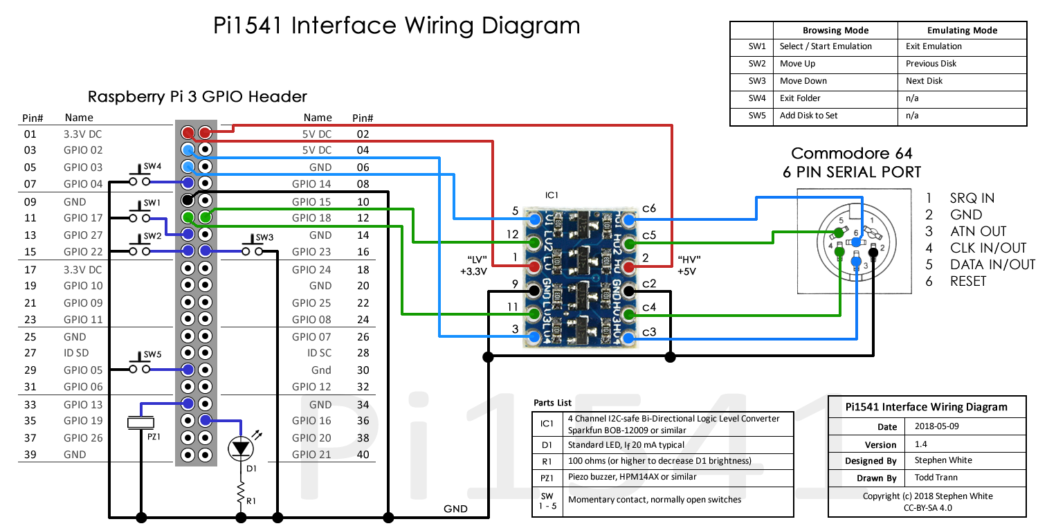
Power the Pi with a suitable external power supply. The I2C Bi-Directional Logic Level Converter gets its 5V from Pi pin 2 and 3.3V from PI pin 1. Both side GNDs and the C64's GND serial port pin 2 are connected to the PI pin 9.
C64's ATN serial port pin 3 is connected to a free 5v side pin of the level converter and the 3.3v side is then connected to the Pi's pin 3 (GPIO02).
C64's CLOCK serial port pin 4 is connected to a free 5v side pin of the level converter and the 3.3v side is then connected to the Pi's pin 11 (GPIO17).
C64's DATA serial port pin 5 is connected to a free 5v side pin of the level converter and the 3.3v side is then connected to the Pi's pin 12 (GPIO18).
C64's RESET serial port pin 6 is connected to a free 5v side pin of the level converter and the 3.3v side is then connected to the Pi's pin 5 (GPIO03).
The buttons/switches, piezo buzzer and LED are all optional.
Option B
This option uses a 7406 just like all Commodore equipment and can therefore support more devices connected to the serial bus.
(Note: you can also use a 7405, 7416, 74LS05, 74LS06 or a 74LS16)
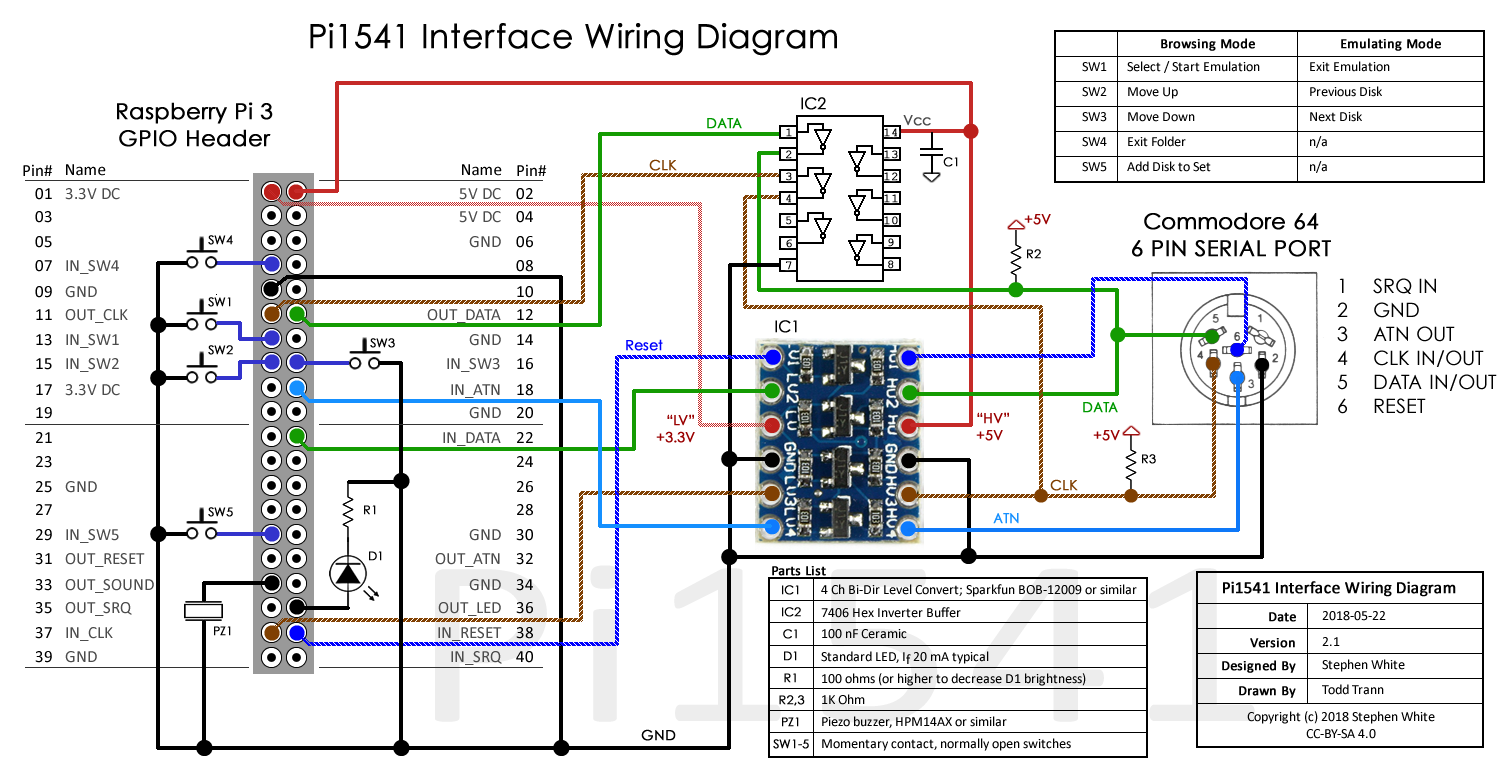 Again, the buttons/switches, piezo buzzer and LED are all optional.
If you build option B you will need to place the line "splitIECLines = 1" in the options.txt file found in the root folder of the SD card.
Buttons/Switches
Optionally you can connect momentary contact buttons that can aid in the use of the Pi1541.
(these are optional and are not required if you are going to use a USB keyboard connected to your Pi)
The buttons are connected like so;-
- Reset (or Select) Pi's pin 13 (GPIO27)
- Previous Disk (or Move Up) Pi's pin 15 (GPIO22)
- Next Disk (or Move Down) Pi's pin 16 (GPIO23)
- Exit Folder Pi's pin 7 (GPIO04)
- Insert Disk Pi's pin 29 (GPIO05)
The other side of the button is connected to ground. (Internal pullups are used so you don't need resistors)
Parts
You could build your own Pi hat following the above schematic with the following parts;-
Search for;-
"Raspberry Pi 3 Model 3 (or 3B+) with suitable power supply" x1
"Female S Terminal 6 pin din PCB" x2
"2x20 pin PCB female header" x1 (2.54mm pitch)
"I2C Bi-Directional Logic Level Converter" x1 (4 or 8 channels)
"Micro SD card 8-32GB" x1
"5cm x 7cm Perfboard" x1
"6x6x4.5mm 4 Pin DIP PCB Momentary Switch" x5 (optional)
Using
Once set up, you can optionally connect the Pi to a screen via the HDMI port (also connect a USB keyboard).
You can then use the keyboard to navigate folders and select disk images.
PAGEUP/DOWN help move faster through the folders.
INSERT adds an image into the selected list.
ENTER adds an image into the selected list and enters emulation mode.
ESC exits a mounted image (and emulation mode) (and clears the selections).
BACKSPACE backs out of a folder (and clears the selections).
Whilst in emulation mode, the number keys are used to swap disk images (when multiple images are selected).
Whilst in browse mode, the number keys are used to swap ROM images.
Once an image is mounted you can use the Commodore computer as you would for a disk inserted into a real 1541.
OR
Once the Pi has booted you can simply type LOAD�*�,8 and it will load fb64 (CBM-Browser) and you can use this to navigate folders and select images.
Note
- fb64 can be used to load PRG files.
- you can use CBM-Browser fb20, fb16 etc for other Commodore computers. (just unzip the fb.zip into your card's 1541 folder). You will also need to use the versions I have supplied as I have had to modify the source to add extra error checking so they wait for the Pi to load the image and the emulated 1541 to boot. LOAD"*",8 loads the first file placed into the 1541 folder so make sure the the fb for the comuter you use the most is the first file copied into the 1541 folder when setting up.
- If you power cycle the Pi to reboot it and try to load fb64 and you get �device not found� just try again as the Pi needs a little time to boot.
When using G64s and original disk images most of them were designed to auto run and hence be loaded with LOAD"*",8,1 (Some directories are even empty if you list them). This can confuse CBM Browser so I recommend that once you browse into the disk image of your choice you quit out of CBM Browser by pressing Q and then you can type the obligatory LOAD"*",8,1
Note: some original software prevent their directory from being displayed via the LOAD"$",8 command. These directories will also not work in CBM-Browser.
OPTIONS
A simple text file called options.txt can be placed in the root folder of the SD card.
deviceID
If you want to change the drive ID edit the options.txt file and you can add/uncomment the line;-
deviceID = 9
ROM
You can also load an alternate ROM by copying over other ROM images and adding lines to options.txt with their names, for example;-
ROM2 = Jiffy.bin
ROM3 = d1541II
(You can swap ROMS when you are not in emulation mode - via the keyboard (number keys) )
OnResetChangeToStartingFolder
When using one of the CBM-Browser files to browse folders on the Commodore computer itself you will need to reload it each time the computer is reset. When this option is set to 1, Pi1541 will change back to the \1541 folder each time the emulated 1541 is reset (see reset below).
SoundOnGPIO
When using a Piezo buzzer instead of sound via the Pi's headphone socket then enable this option.
ScreenWidth
ScreenHeight
When using composite video you may want to decrease the resolution.
These options allow you to experiment with screen sizes.
For example, adding these lines will make the text larger;-
ScreenWidth = 512
ScreenWidth = 384
SplitIECLines
This option needs to be set if your hardware is like schamatic B.
InvertIECInputs
This option needs to be set if your hardware is like schamatic B but instead of a voltage level shifter you are using some other devices that inverts the inputs.
USING
If a disk image on the SD card is set to read only then that is the equivalent of the disk being write protected. (Its name will also appear a different colour on the Pi's screen)
The RESET line on Commodore machine's serial port behaves differently between Commodore computers and even different revisions of the same model. The emulated 1541 may not reset when you reset your machine. You can reset via installing a reset switch on the cable and pressing that or simply exit the emulated disk image via the Pi's keyboard. Note: the emulated Pi will always reset when the machine it is connected to is power cycled.
WARNINGS
WARNING: Build at your own risk to your Pi and Commodore equipment.
WARNING: Make sure you are using copies of your disk images as it could trash them!
Please ensure that you use an adequate power supply for the Pi. The Respberry Pi Foundation recomend a 2.5A minimum.
So far, 100% of problems encountered by others in setting up and getting PI1541 working were down to them using an incorrect power supply or attempting to power all kinds of exotic devices through the Pi's USB ports whilst trying to use it.
If the Pi displays the thunder bolt icon then the power supply is insufficient and Pi1541 will probably not work.
Note: some demos can crash some 64s that are susceptible to the VSP bug. This is not caused by Pi1541.
If building option A then please keep in mind;-
"The FET-method to adapt a 3.3V open-drain bus to a 5V-open-drain-bus requires the RPi to sink all the current that the 5V side sources. Not a big deal if it's the only drive connected, but the IEC bus allows connecting multiple drives, printers and plotters at the same time. Using the FET method, all that current of each pull-up resistor needs to be sinked by the RPi pins, which will eventually break."
THANKS
I would like to thank a number of people.
nbla000 for giving me permission to add what I needed to the CBM-Browser.
Pete Rittwage for help, support, advice, code and testing.
Petros Kokotis and Mateusz Malina for above and beyong testing. The high level of compatibility would not have been achieved if it was not for these two guys.
Todd Trann for his testing, as well as, help with diagrams and images.
I also greatly appreciated the advice, testing and feeback from Rene, Greg Dunlap, penfold42 and Thomas Christoph.